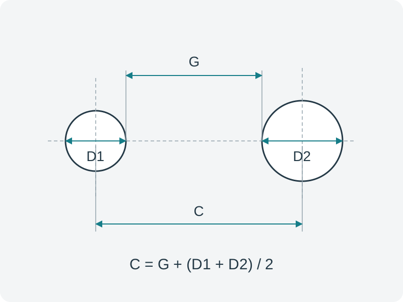
To measure excavator bucket pins for a bucket or quick coupler, use a caliper to record both pin diameters, then record the center-to-center distance (pin centers) and dipper width in mm. Before measuring, identify whether you are checking the machine, a bucket that fits it, or the coupler pickup. These steps describe a two-pin interface; a dedicated coupler pickup needs its own interface drawing. Label every dimension and measurement location in photos or a sketch.
Measure front and rear pin diameter separately
Measure only with the equipment safely isolated and supported according to its manufacturer instructions. Use a caliper on clean, accessible pin surfaces, identify front and rear, and record each diameter separately. Do not assume the pins match or use a worn area as the final manufacturing dimension.
- Front pin diameter D1: ___ mm
- Rear pin diameter D2: ___ mm
- Note wear or differences between measurement positions
- Photograph the measuring tool and identify the pin
Measure pin centers, including unequal pin diameters
Use the center-to-center dimension on a verified drawing where available. For parallel circular pins, an alternative is the nearest-edge gap G measured along the line joining the two centers in an end view. Add both radii: C = G + (D1 + D2) / 2. For example, G = 200 mm, D1 = 60 mm and D2 = 80 mm give C = 270 mm. This is a calculation example, not a fitment specification.
Measuring from the same side of one pin to the same side of the other gives the center distance only if both diameters are equal. Do not use that shortcut for unequal pins, or substitute a diagonal gap.
- Pin centers C: ___ mm
- Nearest-edge gap G, if used: ___ mm
- Record both diameters alongside the gap
- Confirm unclear or inaccessible geometry with an interface drawing
Record dipper width and mounting-ear inside spacing
Measure the outside width of the dipper at its attachment connection. Separately record the clear inside spacing between the attachment mounting ears at each pin position, noting the narrowest clearance and any spacers. These are different surfaces: label each measurement rather than treating dipper width and ear spacing as interchangeable.
- Dipper width W at the connection: ___ mm
- Inside ear spacing at front pin: ___ mm
- Inside ear spacing at rear pin: ___ mm
- Show spacers, bosses and measurement locations in photos
Send the measurements for an attachment match
Use the contact link below to send the labeled dimensions with the carrier make, model and operating weight, working material and duty cycle. Identify whether a quick coupler will remain fitted and provide its brand, model and pickup drawing where available. Measurements are engineering inputs, not automatic confirmation that an attachment fits.
Review and approve the final interface drawing, tolerances and clearances before cutting or machining begins.
- Carrier make/model and operating weight
- D1, D2, C and W in mm, plus separate ear-spacing measurements
- Coupler details and labeled interface photos or drawing
- Working material, required job, hours or cycles per shift, quantity and destination
Record the interface you actually measured
Identify whether the dimensions came from the machine, a bucket that fits it, or the coupler pickup. If a quick coupler stays on the machine, measurements from the bare dipper alone do not describe the attachment connection. Label photos with the same D1, D2, C and W symbols used in the measurement record.
Record the tool, units and measurement locations. If wear, paint or access prevents a reliable reading, mark that value for confirmation rather than rounding it to a familiar nominal size. Final production dimensions and clearances belong on the approved interface drawing.
- One side-view photo showing both pin positions
- One end-view photo showing the ear spacing and any spacers
- Close-up photos of each diameter measurement and the coupler identification plate, where fitted
- Machine model, coupler model and the source of each dimension on the same record
COMMON BUYER QUESTIONS
What excavator bucket pin dimensions do I need to measure?
Record the front pin diameter D1, rear pin diameter D2, center-to-center distance C and outside dipper width W at the connection, all in mm. Record inside mounting-ear spacing separately at both pin positions. Also identify the carrier and any quick coupler.
How do I measure pin centers accurately?
Use a verified center-to-center drawing dimension. For parallel circular pins, measure the nearest-edge gap G along the line joining the centers in an end view, then calculate C = G + (D1 + D2) / 2 using both pin diameters. Same-side edge spacing equals the center distance only when the two diameters are equal.
Are front and rear excavator bucket pins always the same size?
No. Some machines and attachments use different front and rear pin diameters, so both pins should be measured and labeled separately.
Can I select an excavator bucket from operating weight alone?
No. Operating weight helps identify the carrier class, but pin diameters, pin centers, dipper width, coupler geometry, material and intended duty must also be confirmed.